|
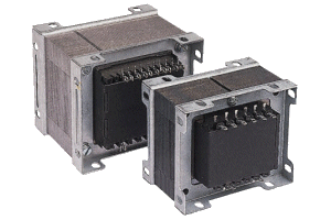
Multi-tapped Secondary, Chassis Mount.
|
|||||||||||||||||||||||||||||||||||||||||||||||||||||
|
Chassis mounting frame construction transformer with multi-tapped secondary voltage designed
according to the following specifications.
Specifications:
|

|
|||||||||||||||||||||||||||||||||
Chassis mounting frame construction low voltage mains transformers with a single 230 VAC 50/60Hz primary
winding and multi-tapped secondary winding. Suitable for a wide range of applications requiring selected
secondary voltages.
When a transformer is used to supply any load other than a pure resistive one, it is necessary to derate its specified AC current rating to prevent overload. These current derating factors are shown below each circuit and relate the transformer ac current rating to the DC load current. Note: Where a transformer has a VA rating, this is the product of the secondary AC voltage and the secondary AC current. DC output voltage of circuits Relationships between VDC and VAC shown below each rectifier circuit do not include losses. The transformer’s ac output voltage is specified at the full load current - off load, the voltage will rise in accordance with the regulation specified for that particular transformer. rectifier ratings For full-wave circuits, the average current per rectifier is 0.5×IDC. For half-wave circuits it equals IDC. For all circuits each rectifier should have a VRRM rating in excess of 1.4×VAC except the half wave capacitor input filter circuit which requires a rating in excess of 2.8×VAC  Relationships and circuits shown above are intended as a guide and assume no circuit losses. For low dc voltages allowance should be made for the diode voltage drop. |
||||||||||||||||||||||||||||||||||
